Draft notes. All dimensions are in millimetres.
Alignment rule — replaces earlier drafts#
Default: notches, sockets and mating connectors share the same grid centre, with symmetric clearance on all sides. The limited edge-aligned notch exception for flat printing is described below. This replaces the earlier left-aligned/top-aligned rule that added all clearance to the right or downward.
- Position geometry by its centre, then extend half its width and height in each direction. Do not use one edge as the clearance anchor under the default rule; only the documented edge exception below permits one-sided relief on a connector; receiving holes stay fixed.
- Receiving holes, sockets and notches keep their 5 mm grid geometry. Only mating connectors are reduced for clearance: 4.8 mm leaves 0.1 mm per side, and 4.6 mm leaves 0.2 mm per side in a 5 mm opening. This replaces the earlier 5.3 mm receiving-opening width and height rule.
- Grid locations such as x = -10 mm and instructions to arrange positions rightwards describe connection centres and layout order, not one-sided clearance.
- The separate blind-socket insertion-depth allowance remains beyond the bar end; it does not offset the cross-sectional centre.
Connecting bars#
- All parts connect using square bars (rods) with a nominal 5 × 5 mm cross-section. Printed male connectors that fit notches must follow the 4.8 mm maximum and centred-clearance rules below.
- Use 2 mm screws throughout.
- A rod's first screw point must be centred exactly 2.5 mm from its end.
- Valid screw-point centres along the rod are 2.5, 5, 7.5, 10 mm, and so on: a 2.5 mm grid measured from that end.
Component reference and grid origin#
- Use the midpoint of each component as the reference for positioning its 5×5 connections, rather than measuring from an outside edge.
- Set the component midpoint to x = 0, with positive x running to the right.
- Place the first nominal rod/socket centre 10 mm to the left of the midpoint, at x = -10 mm.
- Arrange the remaining positions rightwards from there. With the 10 mm centre-to-centre pitch below, the centres are -10, 0, 10, 20 mm, and so on, as needed.
- These positions refer to the nominal 5 mm rods. Socket clearance does not move the grid or its reference points.
Centre the component and expand its sides#
- A component's connectors and notches must always use the shared 5 mm grid for their nominal positions. Do not move connection features off the grid to accommodate the body shape or size.
- If the current body dimensions do not allow grid-aligned connections, expand the sides until the alignment is achieved. Add material or increase the side margins rather than shifting the connector or notch away from its grid position.
- Centre the component itself between those sides, keeping the left/right and top/bottom allowances equal. Grow the enclosing sides symmetrically so the body remains centred on its reference.
- When a holder or enclosure is enlarged to reach the grid, re-centre the item inside it and its receiving cavity or mounting position in both axes. Split the extra space equally left/right and top/bottom; do not keep the item anchored at its former top-left position.
- After expansion, check that opposing connection positions still have centre-to-centre spacing in multiples of 5 mm and that both the body and the item inside have equal opposing margins in both axes.
- This defines the nominal design layout. The separate edge-aligned flat-printing exception can introduce a small local assembled-fit offset, but it does not permit off-grid nominal connection positions or asymmetric body placement simply to fit an existing body size.
Negative example: item biased toward the top-left#
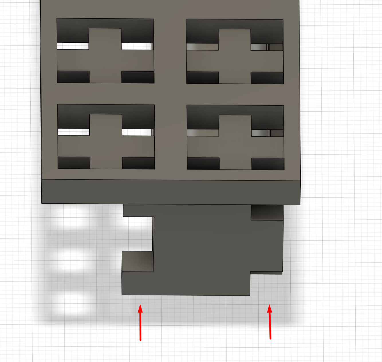
Incorrect: this enlarged holder fits the outer grid, but the item inside remains too far toward the top and left. The unequal opposing margins show that grid-fitting the outside alone is not enough.
Correction: keep the grid-aligned outer connectors and notches fixed, then move the internal item and its cavity or mount to the centre of the enlarged holder. Check left margin = right margin and top margin = bottom margin. This is ordinary component centring, not the limited edge-clearance exception.
Fixed receiving holes; clearance on connectors only#
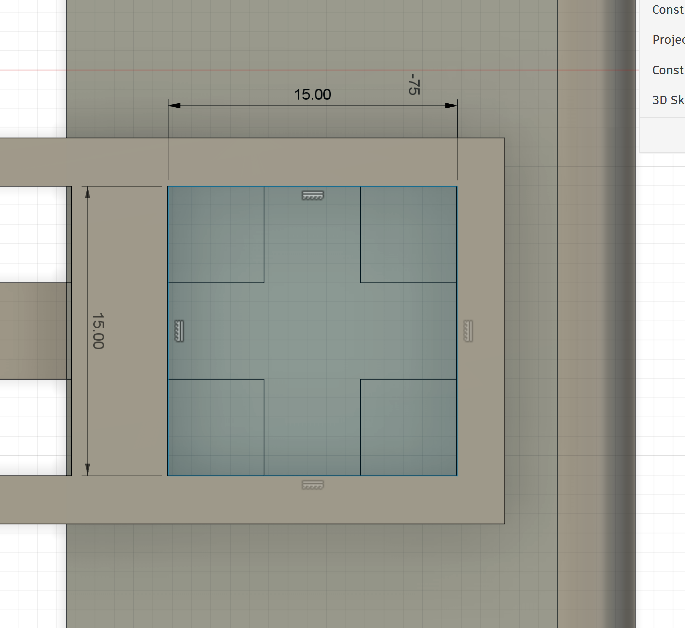
- Receiving holes and notches must always follow the fixed 5 mm grid. Never enlarge, shrink or shift them to obtain fit clearance. A single receiving cell is 5 × 5 mm; larger fitting-hole layouts use whole 5 mm cells, such as the 15 × 15 mm layout below.
- Only the mating connectors vary for fit. Centre each connector on the receiving cell, then reduce its width and height symmetrically. The printed maximum remains 4.8 × 4.8 mm; 4.6 × 4.6 mm is also allowed.
- A 4.6 mm connector starts 0.2 mm inside each edge of its matching 5 mm cell. For a hole spanning 5 to 10 mm, the connector spans 5.2 to 9.8 mm, sharing its 7.5 mm centre. Apply this in both axes.
- Dimension connectors from the matching receiving-hole centres, not by chaining gaps from neighbouring connectors. At 10 mm centre spacing, two centred 4.6 mm connectors have a 5.4 mm edge-to-edge gap; that gap is not a receiving-hole dimension.
- The edge-aligned flat-printing exception may alter a connector only. It must never change a receiving hole's grid position or dimensions.
- This rule concerns the receiving cross-section and grid layout. The separately specified fitting-hole depth and blind-socket insertion-depth allowances remain as stated below.
Grid attachment: notches or a fitting hole#
- A component can attach to the shared grid using notches or a fitting hole.
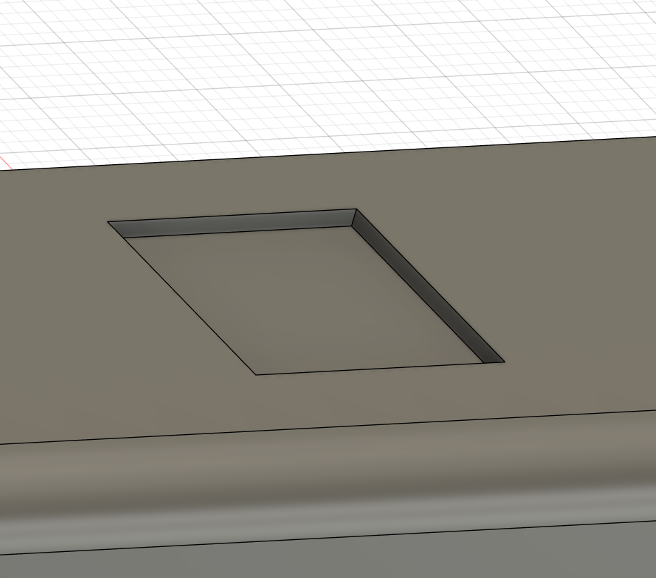
- The 15 × 15 mm fitting hole must be 2 mm deep, measured inward from the receiving surface. This is the fitting-hole depth, separate from the bar-socket engagement depths below.
- The fitting-hole layout has a nominal 15 × 15 mm envelope, with four nominal 5 × 5 mm corner features, one at each corner, as shown below. The four corner regions define the fit around the central cross-shaped opening.
- Keep these features aligned with the shared 5 mm grid. Keep the receiving layout fixed; apply fit clearance only by reducing the mating connectors about their receiving-cell centres.
Notches and printed connectors#
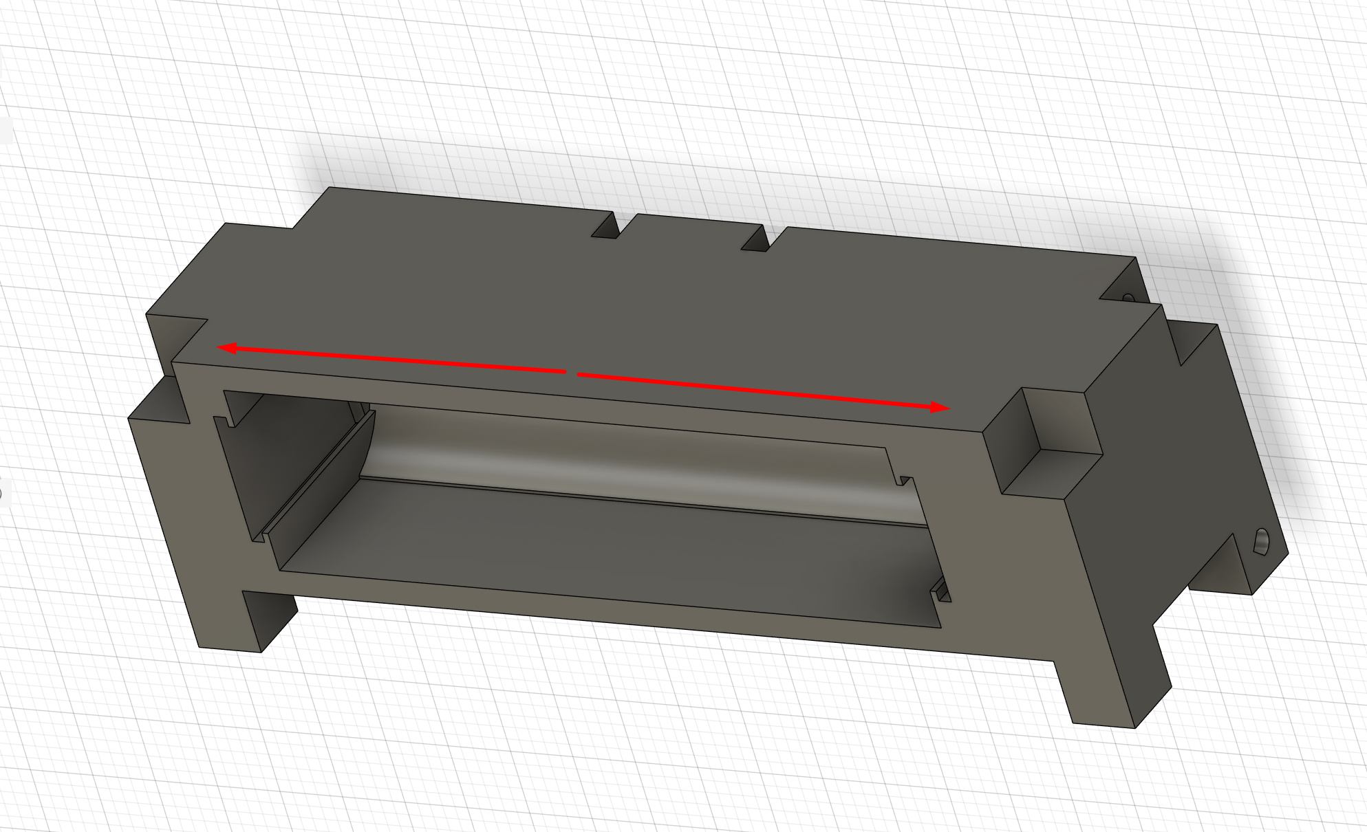
- On any component shape, two separated notches or connectors must have centre-to-centre spacing that is a multiple of 5 mm: 5, 10, 15, 20 mm, and so on. Measure from the shared connection reference, not from an outside edge of the shape.
- Notch centres must align exactly with the 5 mm grid. A holder using the 10 mm pitch described below occupies every second grid position; that pitch is a valid multiple of 5 mm.
- By default, centre each mating connector on the centre of its notch, in both width and height. The edge-aligned flat-printing exception below is the only permitted local departure described here.
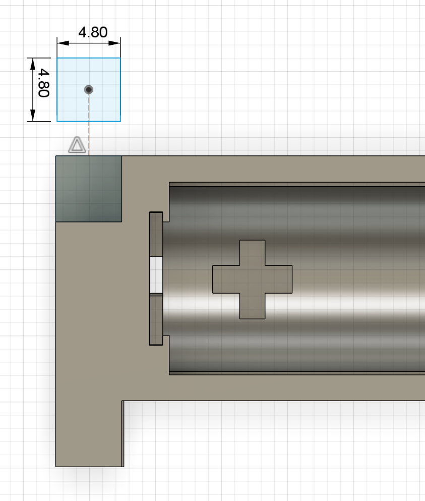
- For 3D-printed male connectors, the cross-section must be no more than 4.8 mm wide and 4.8 mm high.
- Under the default rule, distribute clearance equally on every side. Sketch the connector from the notch centre: a maximum-size connector extends 2.4 mm left, right, above and below that centre. Do not start at a notch edge and measure 4.8 mm inward, which would shift the connector off-centre.
- In a fixed 5 × 5 mm notch, a centred 4.8 × 4.8 mm connector leaves 0.1 mm clearance on each side; a centred 4.6 × 4.6 mm connector leaves 0.2 mm on each side. Do not resize the receiving notch.
- Connector undersizing and socket clearance must not redefine the nominal grid or connection centres. A small local component offset is permitted only for the edge-aligned flat-printing exception below and must be recorded and checked.
Notch spacing example#
The notches on opposite sides of this battery holder use the same 5 mm connection grid, regardless of the surrounding body shape. Their centre-to-centre separation must be a multiple of 5 mm.
Centred printed connector example#
The connector is dimensioned 4.8 × 4.8 mm from its centre, which aligns with the corresponding notch centre.
Edge-aligned notch exception for flat printing#
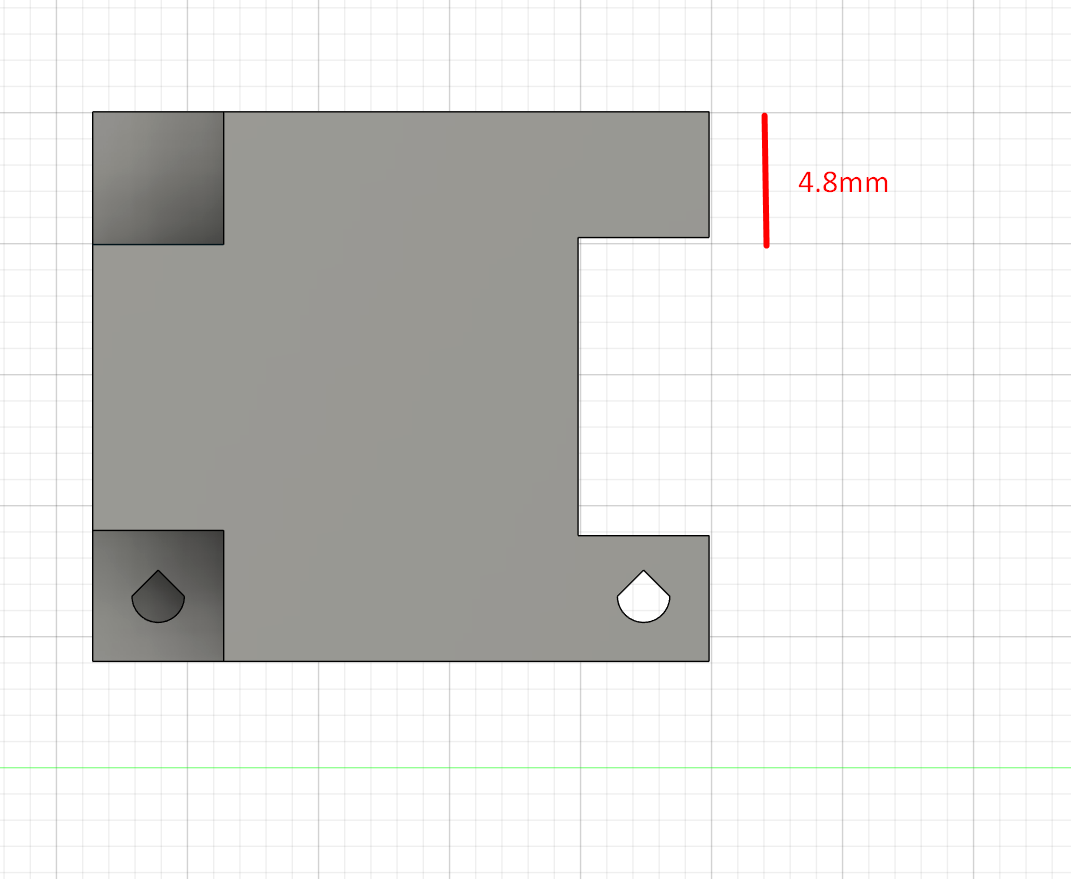
- Use this exception only where a notch is aligned with an outside edge and the normal centred treatment would shift the notch slightly downward or interfere with a flat printing face.
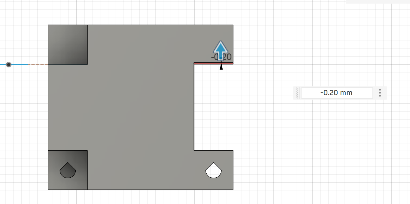
- To keep the print face flat, it is permitted to remove the required clearance from the bottom of the mating connector, keeping its edge-aligned face flush. The receiving notch stays fixed on the 5 mm grid, with unchanged dimensions; do not shift it or cut relief into it.
- This is a limited one-sided vertical clearance exception, not a return to the old general left-alignment rule. Keep the horizontal alignment centred and retain the normal rules everywhere else.
- The 4.8 mm maximum width and height for printed connectors still apply. The diagrams show a 0.20 mm adjustment and a resulting 4.8 mm edge feature as an example; choose the relief for the actual mating geometry.
- The assembled component can sit slightly offset from its nominal grid position as a result. Use the exception carefully and infrequently; do not move the shared grid to hide the offset.
- Record which notch uses the exception, the relief amount and the resulting component offset in the part's design notes.
- Before using it, check that there is enough room for the mating part to fit and be inserted: inspect nearby surfaces and other connectors so the offset does not cause interference, block assembly or force another connection out of alignment. If there is not enough room, retain the standard centred design or revise the surrounding geometry.
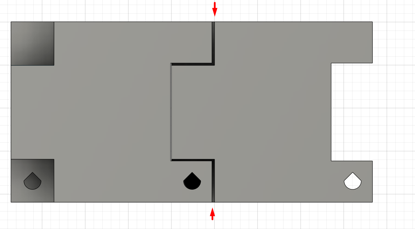
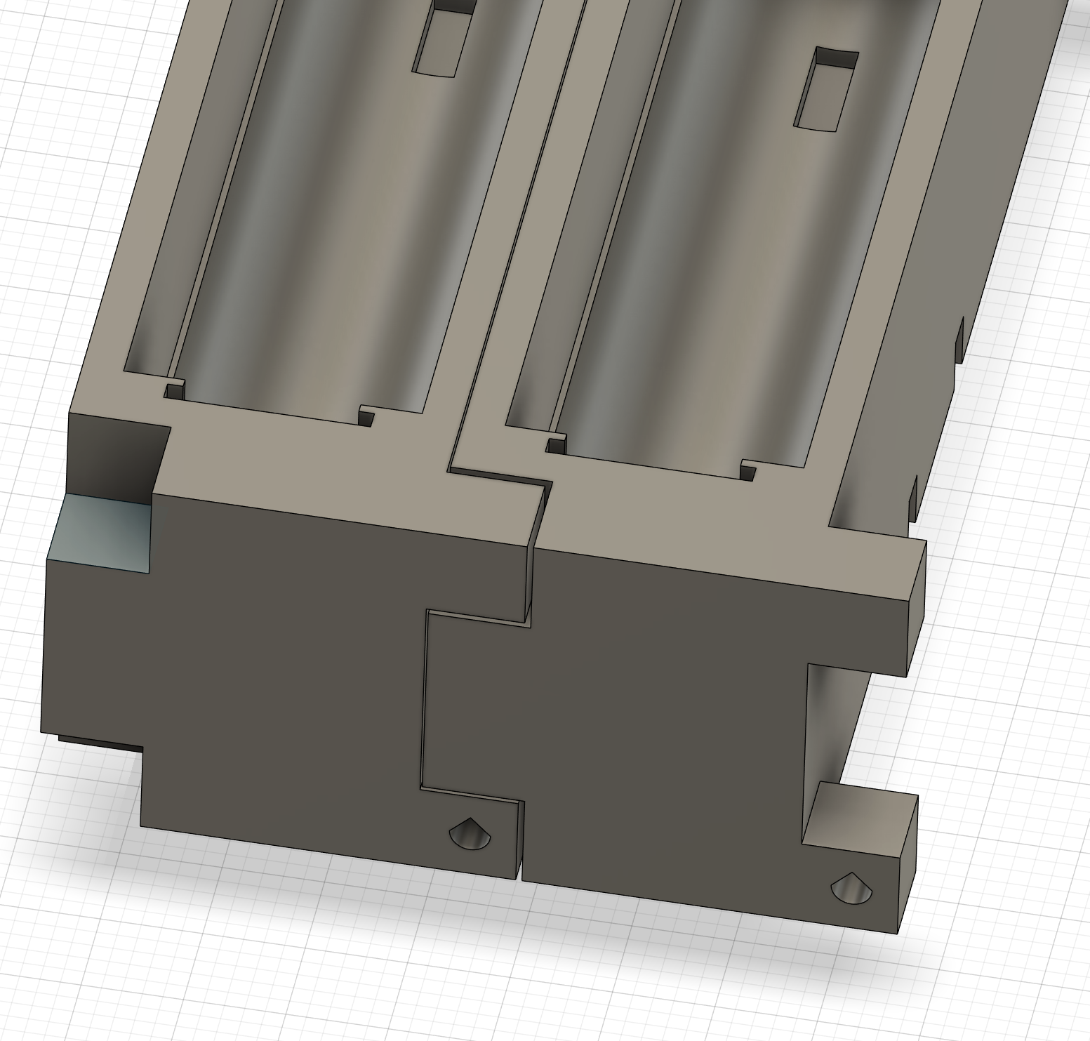
Assembled edge-aligned clearance example#
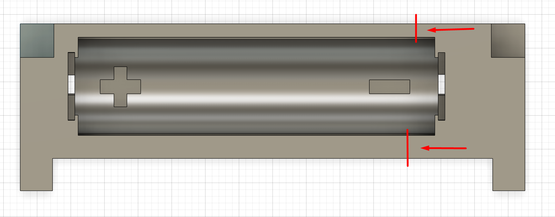
These views show two mating components assembled with edge-aligned connections. The arrows in the plan view highlight the small gaps at the outer ends of the joint; the perspective view shows how the mating features fit together while the outside faces remain aligned.
Use this example to check the complete assembled fit, not just an isolated connector. Confirm that the intended relief leaves room at every mating face and that a small local offset does not make another feature collide or prevent insertion. The images illustrate the edge-aligned exception; they do not introduce a new clearance dimension or replace centred alignment as the default.
Holders and rod spacing#
- In a complex holder, keep 5 mm between adjacent 5 mm rods.
- Draft interpretation: this is the clear gap between nominal rod edges, giving a 10 mm centre-to-centre pitch. Confirm this interpretation before treating the draft as final.
- Receiving rod sockets keep a 5 × 5 mm cross-section, aligned to the shared grid. This supersedes the earlier 5.3 × 5.3 mm opening rule.
- Obtain fit clearance by reducing the mating connector, keeping it centred on the socket. For printed connectors, use no more than 4.8 × 4.8 mm, or 4.6 × 4.6 mm for 0.2 mm per-side clearance.
- For socket centres at -10 and 0 mm, the fixed openings span -12.5 to -7.5 mm and -2.5 to 2.5 mm. Their clear gap remains 5 mm. Centred 4.6 mm connectors span -12.3 to -7.7 mm and -2.3 to 2.3 mm respectively.
Depth and front alignment#
- The nominal connection depth has two options: 5 mm or 10 mm. These are the bar engagement dimensions, before socket clearance.
- Use 10 mm as the preferred starting depth, to leave room for a fillet.
- When components all use the 10 mm nominal depth, align their front faces on a common plane.
- A blind socket that receives a bar must have 0.3 mm of additional insertion-depth clearance: a nominal 5 mm engagement requires a 5.3 mm-deep socket, and a nominal 10 mm engagement requires a 10.3 mm-deep socket.
- Add this clearance beyond the bar's nominal end; it does not change the connection grid or front-face alignment.
Connection height and mounting plates#
- The standard connection block height is 5 mm overall.
- A block without a mounting plate is 5 mm high.
- For a plate-mounted block, use a 1 mm bottom plate and a 4 mm extrusion above it, keeping the total height at 5 mm.
- Hole centres must remain in the same position in either construction: 2.5 mm above the overall bottom and 2.5 mm from the side of the nominal 5 mm block.
- Measure the vertical hole position from the underside of the bottom plate, not from its top surface. With a 1 mm plate, the hole centre is therefore 1.5 mm above the plate's top surface.
Panel screw holes#
- Place the screw-hole centre 2.5 mm from the relevant panel edge.
- The screw opening must be 2 mm wide.
Block fastening and screw lengths#
- Attach connection blocks using screws.
- The wall thickness between the screw entry face and the fastening hole may vary between components.
- Keep a selection of 2 mm screws in different lengths, including very long screws, so the screw length can accommodate the wall thickness and reach the fastening point.
- Choose the screw length to suit the part. Do not introduce awkward shapes, recesses or extensions solely to fit a shorter screw when they would require supports or add printing complexity.
Cabling channels#
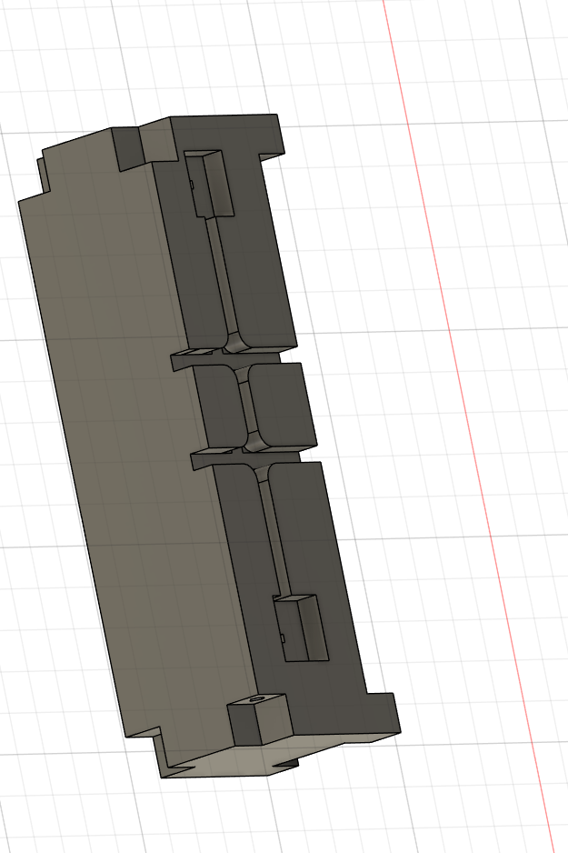
- Cable-routing channels must be 3 mm deep and 2 mm wide.
- Where possible, cut the channel into the bottom of the component, meaning the face intended to rest on the printer bed during printing.
- Measure channel depth inward from that bottom face and width across the cable route. The 3 mm channel depth is separate from the connection engagement and socket-depth dimensions.
Printing and hole geometry#
- Every object must have a clearly defined intended print orientation, identifying the side or face that rests on the print bed.
- Design the object for that orientation and minimize the need for printing supports.
- Use teardrop-shaped holes to reduce support requirements, oriented for the intended print direction.
- Square rod sockets must still accommodate the specified 5 × 5 mm bar. Any teardrop relief must preserve that fit; its exact profile remains to be defined.
- Wherever possible, make holes pass all the way through the object.
- If a rod socket must stop inside the object, use 5.3 mm or 10.3 mm actual socket depth for the corresponding 5 mm or 10 mm nominal engagement. The 10 mm nominal option is preferred.
Visual example#
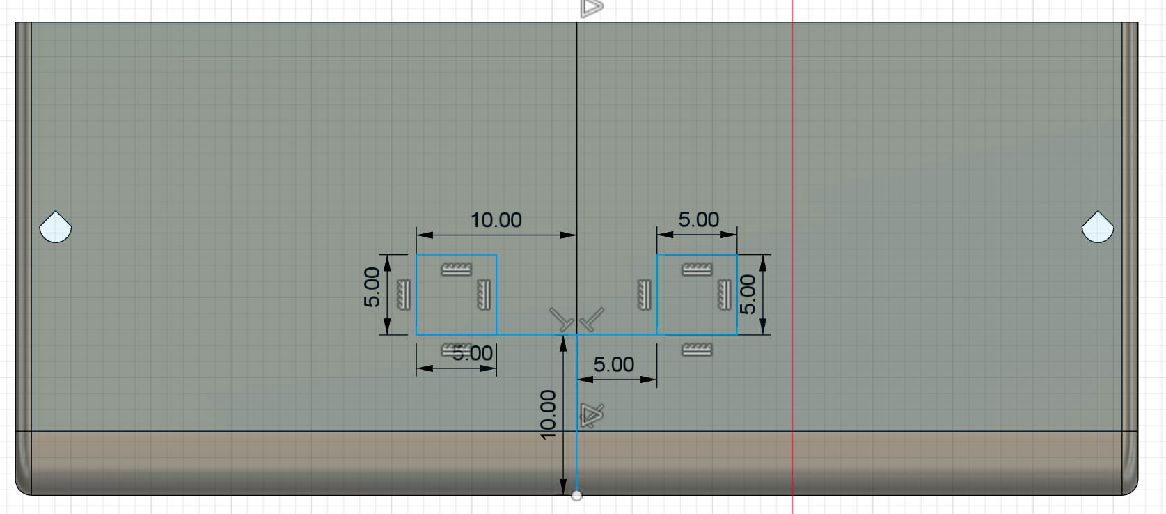
Four-block holder#
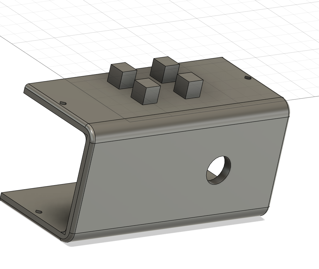
A four-block holder with four nominal 5 × 5 mm connection positions, arranged in two rows. The drawing shows the horizontal spacing and the 10 mm depth references.
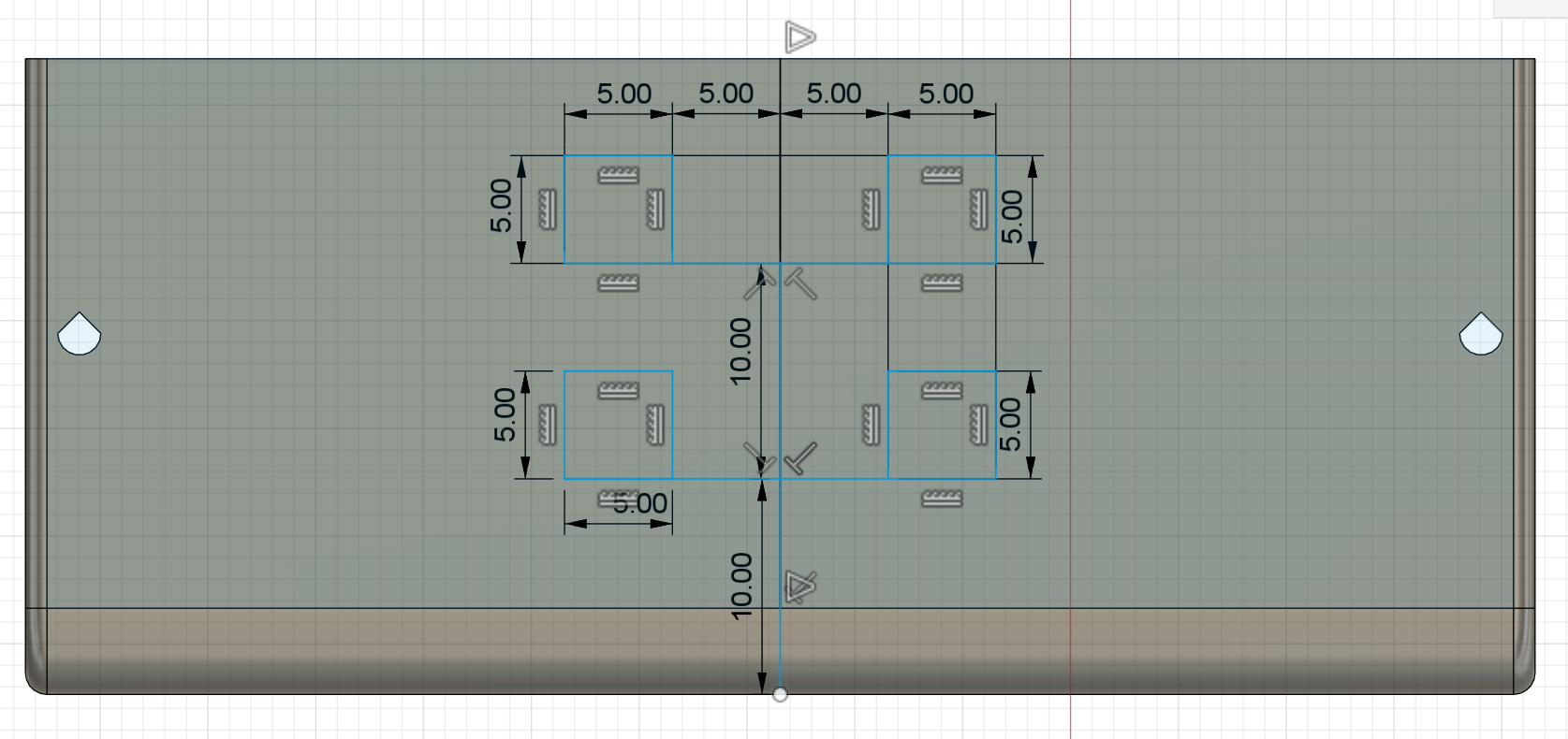
Plate-mounted four-block holder#
The completed holder illustrates four connection blocks on a mounting plate. Each connection keeps the standard 5 mm total height: 1 mm of plate plus 4 mm of extrusion. Hole centres retain the same 2.5 mm bottom and side offsets as a block without a plate.